Add Data To Circuits
The GlobalNOC Worldvie Panel allows multiple data points to be mapped to a particular circuit which can then be displayed on its tooltip like this example below:
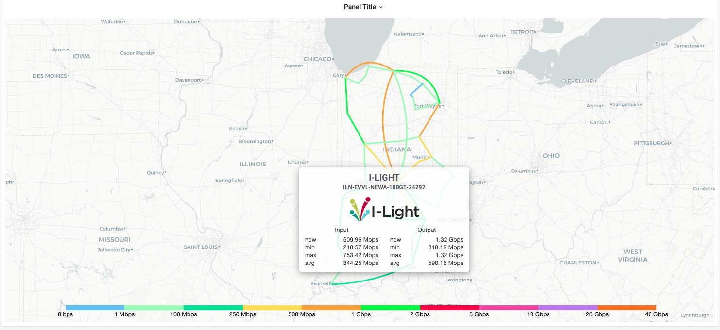
In the example above, the tooltip has two different metrics applied to it namely Input and Output. Let's walk through how to apply these datapoints to a worldview map.
All grafana datasources send the panel an array of datapoints like the example below:
[ { "name": "hostname.a.b.c+interfaceET-12+input", "datapoints": [[1856397.26666666, 1633959000], [1650972.84444445, 1633958640], [1373735.42222222, 1633958280],…] }, { "name": "hostname.a.b.c+interfaceGE-42+input", "datapoints": [[1856397.26666666, 1633959000], [1650972.84444445, 1633958640], [1373735.42222222, 1633958280],…] }, { "name": "hostname.a.b.c+interfaceET-12+output", "datapoints": [[19015224.4666666, 1633959000], [16855873.2777778, 1633958640], [15234882.4222223, 1633958280],…] }, { "name": "hostname.d.e.f+interfaceET-45+input", "datapoints": [[986576809.333332, 1633959000], [913103824.399999, 1633958640], [890706239.466668, 1633958280],…] }, ...]To apply say the first two data points from the example above, the circuit map json should look something like this:
"adjacencies": [ ..., { "id": "O2LPdq", // Circuit ID "anchors": [ // Circuit Path Anchors (This example shows a Cubic [C] bezier curve) // That will be drawn with the anchors below between Chicago and Amsterdam "C", [62.42273329229529, -79.98046875000001], [67.73918797934685, -13.183593750000002] ], "a": "8PrAEX", // Chicago Endpoint ID "b": "0ZUNVC", // Amsterdam Endpoint ID "label": "Chicago - Amsterdam", // Circuit Label "metadata": { // Circuit specific metadata "data_targets": [ "hostname.a.b.c+interfaceET-12+input", // Will be used to calculate circuit `Input` "hostname.a.b.c+interfaceGE-42+input", // Will be used to calculate circuit `Input` "hostname.a.b.c+interfaceET-12+output" // Will be used to calculate circuit `Output` ] }, "min": 0, // Minimum Circuit Speed "max": 10000000000 // Maximum Circuit Speed }, ...],...Each circuit should have a metadata.data_targets property on it that will be an list of the exact target names of the datapoints it expects to receive from its respective datasource.
Once the data_targets property has been set correctly, Head on over to the panel settings to divide the datapoints that will be mapped to the circuits into two groups: Input and Output. Open the Data Settings tab on the panel settings sidebar and add these two aggregate groups:
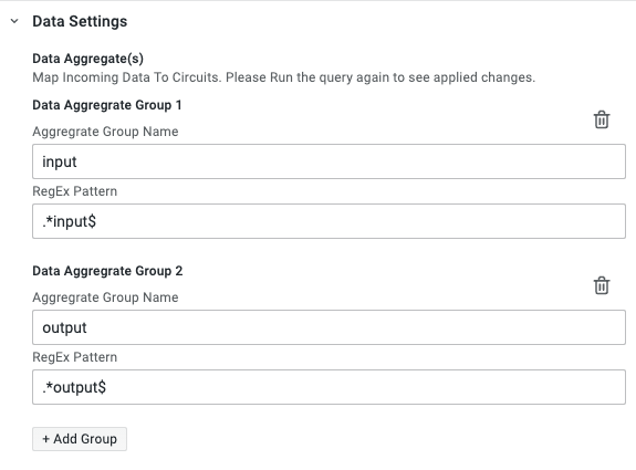
Setting these aggregate groups will now map the data_targets names that end with input (hostname.a.b.c+interfaceET-12+input, hostname.a.b.c+interfaceGE-42+input) to the Input group and names that end with output (hostname.a.b.c+interfaceET-12+input) to the Output group